Hands-On IoT Hacking: Rapid7 at DEF CON 30 IoT Village, Part 1

Rapid7 was back this year at DEF CON 30 participating at the IoT Village with another hands-on hardware hacking exercise, with the goal of teaching attendees' various concepts and methods for IoT hacking. Over the years, these exercises have covered several different embedded device topics, including how to use a Logic Analyzer, extracting firmware, and gaining root access to an embedded IoT device.

Like last year, we had many IoT Village attendees request a copy of our exercise manual, so again I decided to create an in-depth write-up about the exercise we ran, with some expanded context to answer several questions and expand on the discussion we had with attendees at this year's DEF CON IoT Village.

This year's exercise focused on the following key areas:

  • Interaction with eMMC in circuit
  • Using Linux dd command to make binary copy of flash memory
  • Use unsquashfs and mksquashfs commands to unpack and repack read only squash file systems
  • Alter startup files within the embedded Linux operating system to execute code during device startup
  • Leverage dropbear to enable SSH access

Summary of exercise

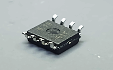
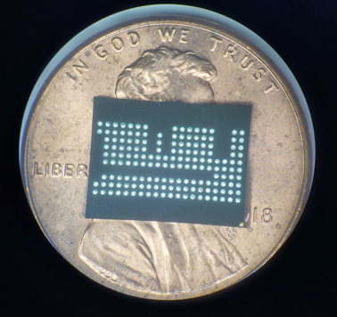
The goal of this year's hands-on hardware hacking exercise was to gain root access to a Arris SB6190 Cable modem without needing to install any external code. To do this, the user interacted with the device via a PHISON PS8211-0 embedded multimedia controller (eMMC) to mount up and gain access to the NAND flash memory storage. With NAND flash memory access, the user was able to identify the partitions of interest and extract those partitions using the Linux dd command.

Next, the user extracted the filesystem from the partition binary files and was then able to modify key elements to enable SSH access over the ethernet connection. After the modification where completed the filesystems were repacked and written back to the modem device. Finally, the attendee was able to power up the device and login over ethernet using SSH with root access and default device password.

Hands-On IoT Hacking: Rapid7 at DEF CON 30 IoT Village, Part 1

eMMC access to flash memory

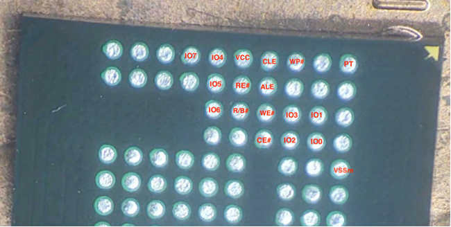
In this first section of the exercise, we focused on understanding the process of gaining access to the NAND flash memory by interacting with a PHISON PS8211-0 embedded multimedia controller (eMMC).

Wiring up eMMC and SD card breakout board

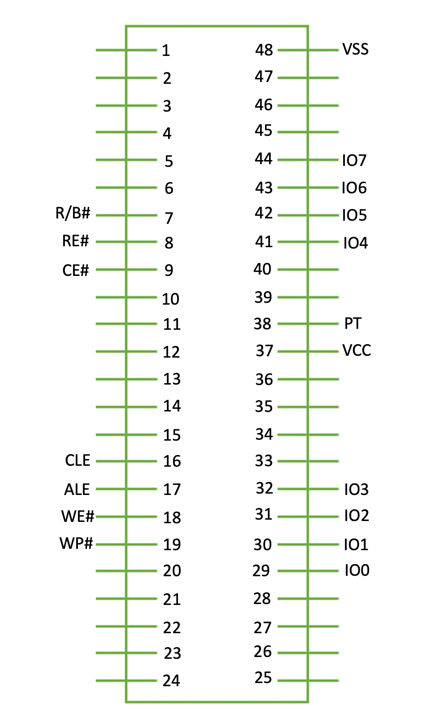
To interact with typical eMMC devices, we typically need the following connections.

  • CMD Command
  • DAT Data
  • CLK Clock
  • VCC Voltage 3.3v
  • VCCq Controller Voltage 1.8v – 3.3v
  • GND Ground

As shown in the above bullets, there are typically two different voltages required to interact with eMMC chips. However, in this case, we determined that the PHISON PS8211-0 eMMC chip did not have a different controller voltage for VCCq, meaning that the voltage used was only 3.3v for this example.

When connecting to and interacting with an eMMC device, we usually can utilize the internal power supply of the device. This often works well when different VCC and VCCq voltages are required, but in those cases, we also have to hold the microcontroller unit (MCU) at reset state to prevent the processor from causing interruption when trying to read memory. In this example, we found that the PHISON eMMC chip and NAND memory could be powered by supplying the voltage externally via the SD Card reader.

When using an SD Card reader to supply voltage, we must avoid hooking up the device's normal source of power also. Hooking both sources – normal and SD Card – into the devices will lead to permanent damage to the device.

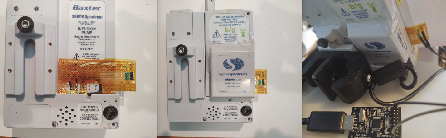
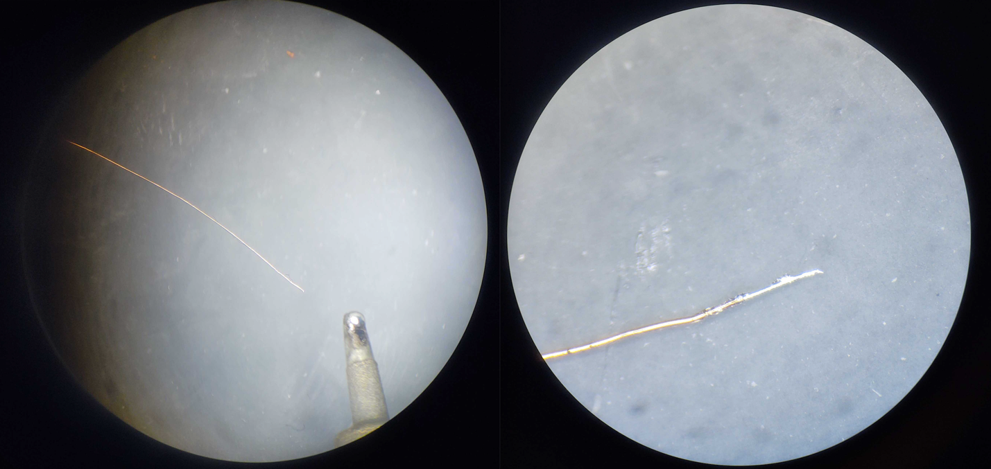
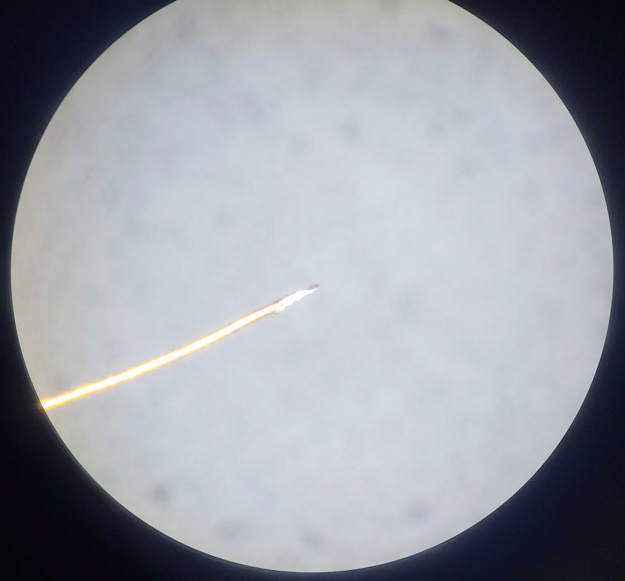
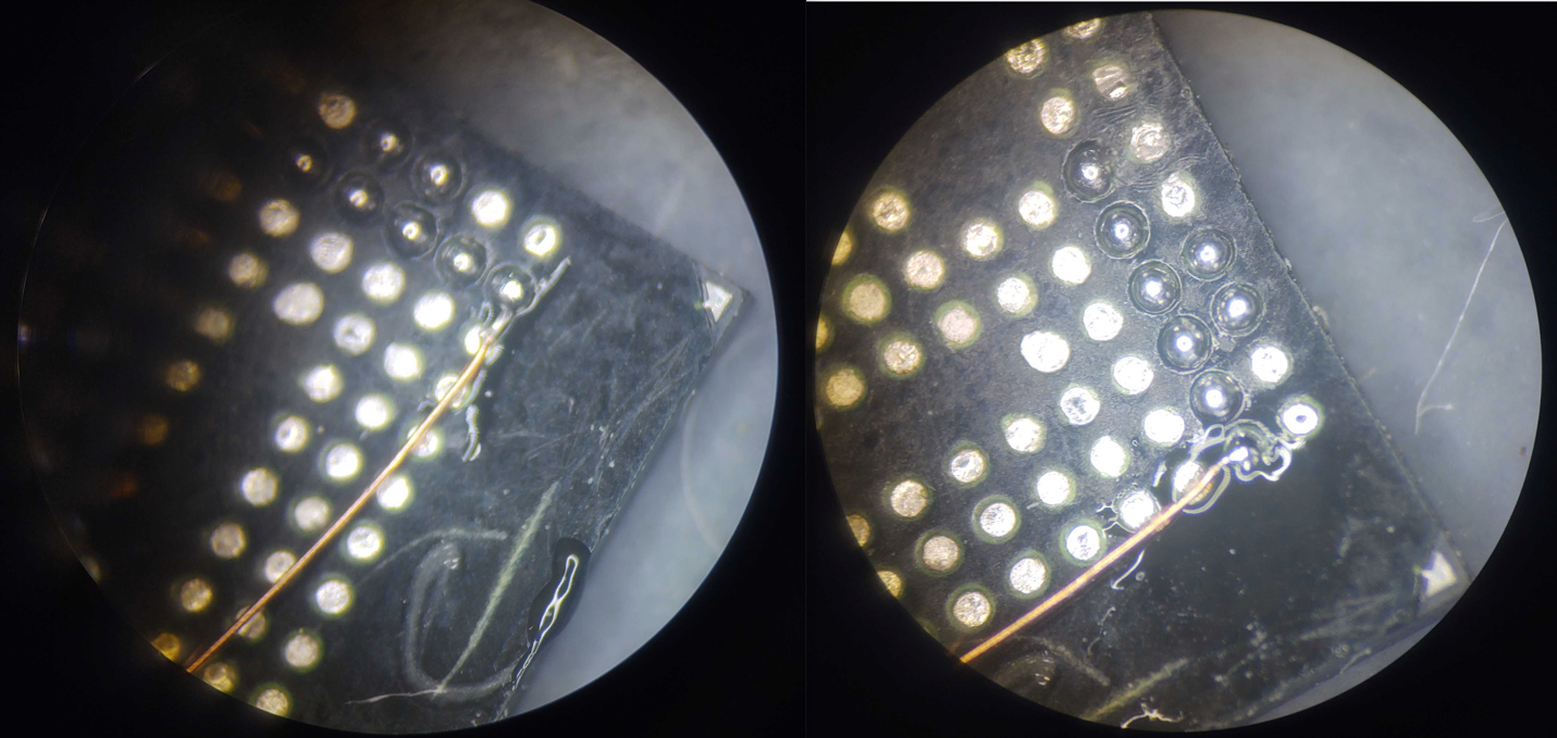
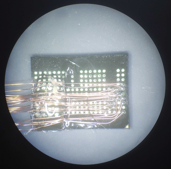
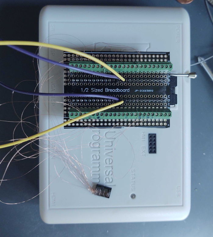
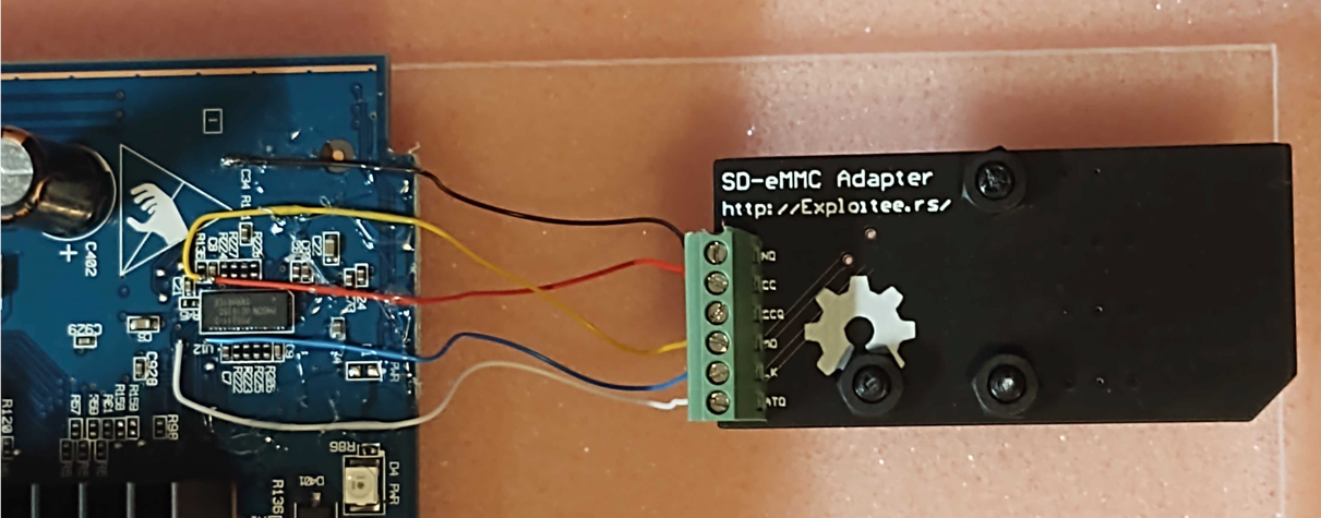
When it comes to soldering the needed wiring for this exercise, we realized allowing attendees to do the soldering connection would be much more complex than we could support. So, all the wiring was presoldered before the IoT Village event using 30-gauge color-coded wirewrap wire. This wiring was then attached to a SD Card breakout board as shown below in Figure 1:

  • White = Data
  • Blue = Clock
  • Yellow = Command
  • Red = Voltage (VCC)
  • Black = Ground
Hands-On IoT Hacking: Rapid7 at DEF CON 30 IoT Village, Part 1
Figure 1: Wiring Hookups

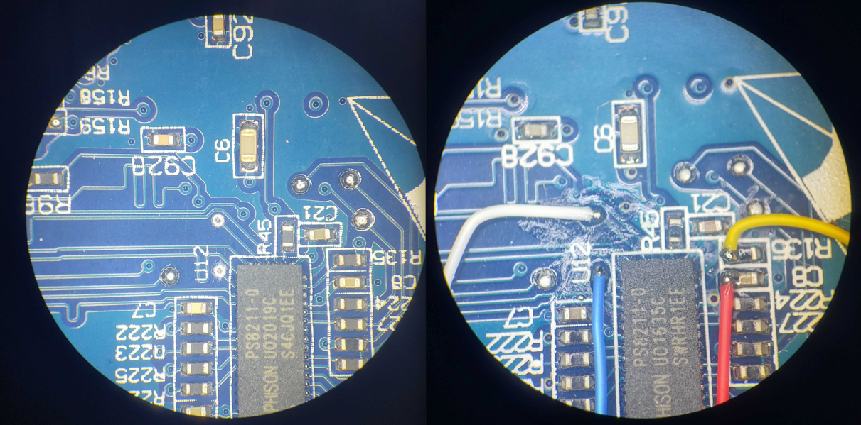
Also, as you can see in the above images, the wires do not run parallel against each other, but have a reasonable gap between them and pass over each other perpendicularly when they cross over. This is because we found during testing that if we ran wires directly next to each other, it caused the partitions to fail to mount properly, most likely because noise was induced into the lines from the other lines affecting the signal.

Note: If you are looking to do your own wiring, the 30-gauge wirewrap wire I used is a Polyvinylidene fluoride coated insulation wire under the brand name of Kynar. The benefit of using Kynar wirewrap is that this insulation does not melt or shrink as easily from heat from the solder iron. When heated by a solder iron, standard plastic-coated insulation will shrink back, exposing uninsulated wire. This can lead to wires shorting out on the circuit board.

Connect SD card reader

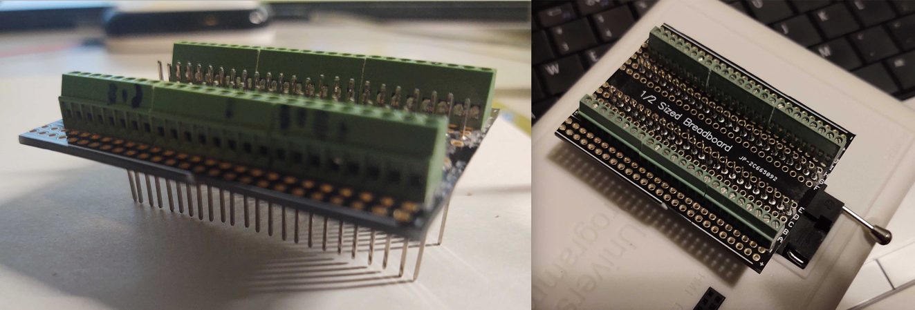
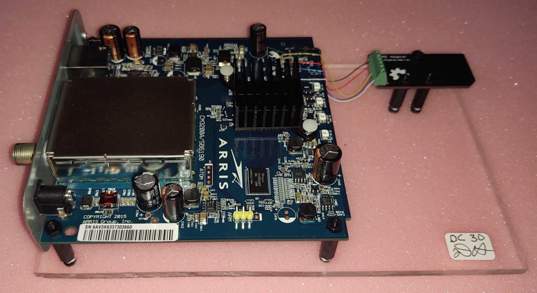
With the modem wired up to SD Card breakout as shown above we can mount NAND flash memory by connecting a SD Card reader. Note, not all SD Card readers will work, I used a simple trial and error method with several SD Card readers I had in my possession until I found that an inexpensive DYNEX brand reader worked. It should be attached as shown below in Figure 2:

Hands-On IoT Hacking: Rapid7 at DEF CON 30 IoT Village, Part 1
Figure 2: Connected SD Card Reader

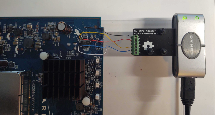
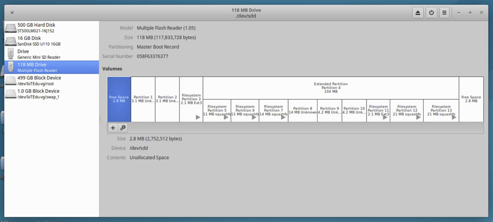
Once plugged in, the various partitions on the Cable modem NAND Flash memory should start loading. In this case a total of seven partitions mounted up. This can take a few minutes to complete. If your system opened each one of the volumes as it mounted, I typically shut them down to avoid all the confusion on your system desktop. To see the layout of the various partitions on the NAND Flash and gather information as needed for reading and writing to the correct partitions. We used the Linux application Disks. Once Disks is opened you can click on the 118 MB Drive in the left column, and it will show all of the partitions and should look something like Figure 3 below:

Hands-On IoT Hacking: Rapid7 at DEF CON 30 IoT Village, Part 1
Figure 3: Disks NAND Flash Partitions

In our second installment of this 4-part blog series, we'll discuss the step of extracting partition data. Check back with us next week!

Baxter SIGMA Spectrum Infusion Pumps: Multiple Vulnerabilities (FIXED)

Rapid7, Inc. (Rapid7) discovered vulnerabilities in two TCP/IP-enabled medical devices produced by Baxter Healthcare. The affected products are:

  • SIGMA Spectrum Infusion Pump (Firmware Version 8.00.01)
  • SIGMA Wi-Fi Battery (Firmware Versions 16, 17, 20 D29)

Rapid7 initially reported these issues to Baxter on April 20, 2022. Since then, members of our research team have worked alongside the vendor to discuss the impact, resolution, and a coordinated response for these vulnerabilities.

Product description

Baxter’s SIGMA Spectrum product is a commonly used brand of infusion pumps, which are typically used by hospitals to deliver medication and nutrition directly into a patient’s circulatory system. These TCP/IP-enabled devices deliver data to healthcare providers to enable more effective, coordinated care.

Credit

The vulnerabilities in two TCP/IP-enabled medical devices were discovered by Deral Heiland, Principal IoT Researcher at Rapid7. They are being disclosed in accordance with Rapid7’s vulnerability disclosure policy after coordination with the vendor.

Vendor statement

"In support of our mission to save and sustain lives, Baxter takes product security seriously. We are committed to working with the security researcher community to verify and respond to legitimate vulnerabilities and ask researchers to participate in our responsible reporting process. Software updates to disable Telnet and FTP (CVE-2022-26392) are in process. Software updates to address the format string attack (CVE-2022-26393) are addressed in WBM version 20D30 and all other WBM versions. Authentication is already available in Spectrum IQ (CVE-2022-26394). Instructions to erase all data and settings from WBMs and pumps before decommissioning and transferring to other facilities (CVE-2022-26390) are in process for incorporation into the Spectrum Operator’s Manual and are available in the Baxter Security Bulletin."

Exploitation and remediation

This section details the potential for exploitation and our remediation guidance for the issues discovered and reported by Rapid7, so that defenders of this technology can gauge the impact of, and mitigations around, these issues appropriately.

Battery units store Wi-Fi credentials (CVE-2022-26390)

Rapid7 researchers tested Spectrum battery units for vulnerabilities. We found all units that were tested store Wi-Fi credential data in non-volatile memory on the device.

When a Wi-Fi battery unit is connected to the primary infusion pump and the infusion pump is powered up, the pump will transfer the Wi-Fi credential to the battery unit.

Exploitation

An attacker with physical access to an infusion pump could install a Wi-Fi battery unit (easily purchased on eBay), and then quickly power-cycle the infusion pump and remove the Wi-Fi battery – allowing them to walk away with critical Wi-Fi data once a unit has been disassembled and reverse-engineered.

Also, since these battery units store Wi-Fi credentials in non-volatile memory, there is a risk that when the devices are de-acquisitioned and no efforts are made to overwrite the stored data, anyone acquiring these devices on the secondary market could gain access to critical Wi-Fi credentials of the organization that de-acquisitioned the devices.

Remediation

To mitigate this vulnerability, organizations should restrict physical access by any unauthorized personnel to the infusion pumps or associated Wi-Fi battery units.

In addition, before de-acquisitioning the battery units, batteries should be plugged into a unit with invalid or blank Wi-Fi credentials configured and the unit powered up. This will overwrite the Wi-Fi credentials stored in the non-volatile memory of the batteries. Wi-Fi must be enabled on the infusion pump unit for this overwrite to work properly.

Format string vulnerabilities

“Hostmessage” (CVE-2022-26392)

When running a telnet session on the Baxter Sigma Wi-Fi Battery Firmware Version 16, the command “hostmessage” is vulnerable to format string vulnerability.

Exploitation

An attacker could trigger this format string vulnerability by entering the following command during a telnet session:

Baxter SIGMA Spectrum Infusion Pumps: Multiple Vulnerabilities (FIXED)

To view the output of this format string vulnerability, `settrace state=on` must be enabled in the telnet session. `set trace` does not need to be enabled for the format string vulnerability to be triggered, but it does need to be enabled if the output of the vulnerability is to be viewed.

Once `set trace` is enabled and showing output within the telnet session screen, the output of the vulnerability can be viewed, as shown below, where each `%x` returned data from the device’s process stack.

Baxter SIGMA Spectrum Infusion Pumps: Multiple Vulnerabilities (FIXED)

SSID (CVE-2022-26393)

Rapid7 also found another format string vulnerability on Wi-Fi battery software version 20 D29. This vulnerability is triggered within SSID processing by the `get_wifi_location (20)` command being sent via XML to the Wi-Fi battery at TCP port 51243 or UDP port 51243.

Baxter SIGMA Spectrum Infusion Pumps: Multiple Vulnerabilities (FIXED)

Exploitation

This format string vulnerability can be triggered by first setting up a Wi-Fi access point containing format string specifiers in the SSID. Next, an attacker could send a `get_wifi_location (20)` command via TCP Port 51243 or UDP port 51243 to the infusion pump. This causes the device to process the SSID name of the access point nearby and trigger the exploit.  The results of the triggering of format strings can be viewed with trace log output within a telnet session as shown below.

Baxter SIGMA Spectrum Infusion Pumps: Multiple Vulnerabilities (FIXED)

The SSID of `AAAA%x%x%x%x%x%x%x%x%x%x%x%x%x%x` allows for control of 4 bytes on the stack, as shown above, using the `%x` to walk the stack until it reaches 41414141. By changing the leading `AAAA` in the SSID, a malicious actor could potentially use the format string injection to read and write arbitrary memory. At a minimum, using format strings of `%s` and `%n` could allow for a denial of service (DoS) by triggering an illegal memory read (`%s`) and/or illegal memory write (`%n`).

Note that in order to trigger this DoS effect, the attacker would need to be within normal radio range and either be on the device's network or wait for an authorized `get_wifi_location` command (the latter would itself be a usual, non-default event).

Remediation

To prevent exploitation, organizations should restrict access to the network segments containing the infusion pumps. They should also monitor network traffic for any unauthorized host communicating over TCP and UDP port 51243 to infusion pumps. In addition, be sure to monitor Wi-Fi space for rogue access points containing format string specifiers within the SSID name.

Unauthenticated network reconfiguration via TCP/UDP (CVE-2022-26394)

All Wi-Fi battery units tested (versions 16, 17, and 20 D29) allowed for remote unauthenticated changing of the SIGMA GW IP address. The SIGMA GW setting is used for configuring the back-end communication services for the devices operation.

Exploitation

An attacker could accomplish a remote redirect of SIGMA GW by sending an XML command 15 to TCP or UDP port 51243. During testing, only the SIGMA GW IP was found to be remotely changeable using this command. An example of this command and associated structure is shown below:

Baxter SIGMA Spectrum Infusion Pumps: Multiple Vulnerabilities (FIXED)

This could be used by a malicious actor to man-in-the-middle (MitM) all the communication initiated by the infusion pump. This could lead to information leakage and/or data being manipulated by a malicious actor.

Remediation

Organizations using SIGMA Spectrum products should restrict access to the network segments containing the infusion pumps. They should also monitor network traffic for any unauthorized host communicating over TCP and UDP port 51243 to the infusion pumps.

UART configuration access to Wi-Fi configuration data (additional finding)

The SIGMA Spectrum infusion pump unit transmits data unencrypted to the Wi-Fi battery unit via universal asynchronous receiver-transmitter (UART). During the power-up cycle of the infusion pump, the first block of data contains the Wi-Fi configuration data. This communication contains the SSID and 64-Character hex PSK.

Baxter SIGMA Spectrum Infusion Pumps: Multiple Vulnerabilities (FIXED)

Exploitation

A malicious actor with physical access to an infusion pump can place a communication shim between the units (i.e., the pump and the Wi-Fi battery) and capture this data during the power-up cycle of the unit.

Baxter SIGMA Spectrum Infusion Pumps: Multiple Vulnerabilities (FIXED)

Remediation

To help prevent exploitation, organizations should restrict physical access by unauthorized persons to the infusion pumps and associated Wi-Fi battery units.

Note that this is merely an additional finding based on physical, hands-on access to the device. While Baxter has addressed this finding through better decommissioning advice to end users, this particular issue does not rank for its own CVE identifier, as local encryption is beyond the scope of the hardware design of the device.

Disclosure timeline

Baxter is an exemplary medical technology company with an obvious commitment to patient and hospital safety. While medtech vulnerabilities can be tricky and expensive to work through, we're quite pleased with the responsiveness, transparency, and genuine interest shown by Baxter's product security teams.

  • April, 2022: Issues discovered by Deral Heiland of Rapid7
  • Wed, April 20, 2022: Issues reported to Baxter product security
  • Wed, May 11, 2022: Update requested from Baxter
  • Wed, Jun 1, 2022: Teleconference with Baxter and Rapid7 presenting findings
  • Jun-Jul 2022: Several follow up conversations and updates between Baxter and Rapid7
  • Tue, Aug 2, 2022: Coordination tracking over VINCE and more teleconferencing involving Baxter, Rapid7, CERT/CC, and ICS-CERT (VU#142423)
  • Wed, Aug 31, 2022: Final review of findings and mitigations
  • Thu Sep 8, 2022: Baxter advisory published
  • Thu, Sep 8, 2022: Public disclosure of these issues
  • Thu, Sep 8, 2022: ICS-CERT advisory published

NEVER MISS A BLOG

Get the latest stories, expertise, and news about security today.


Additional reading:

Evaluating the Security of an Enterprise IoT Deployment at Domino's Pizza

Recently, I had a great opportunity to work with Domino's Pizza to evaluate an internally conceived Internet of Things (IoT)-based business solution they had designed and deployed throughout their US store locations. The goal of this research project was to understand the security implications around a large-scale enterprise IoT project and processes related to:

  • Acquisition, implementation, and deployment
  • Technology and functionality
  • Management and support

Laying the groundwork

I sat down with each of the internal teams involved with this project, and we discussed those key areas and how security was defined and applied within each. I gained valuable new insight into how security should play into the design and construction of a large IoT business solution, especially within the planning and acquisition phases. This opportunity allowed me to see how a security-driven organization like Domino's approaches a large-scale project like this.

I walked away from this phase of the project with some great takeaways that should be considered on all like-minded projects:

  • Always consider vendor security in your risk planning and modeling
  • Security “must-haves" should map to your organization's internal security policies

Assessing the security status quo

Also, as part of this research project, I conducted a full ecosystem security assessment, examining all the critical hardware components, operation software, and associated network communications. As with any large-scale enterprise implementation, we did find a few security problems. This is the main reason all projects, even those with security built in from the start, should go through a wide-ranging security assessment to flush out any shortcomings that could be lurking under the hood. Once completed, I delivered a comprehensive report, which the security teams and project developers then used to quickly create solutions for fixing the identified issues.

This also allowed me the chance to observe and discuss the processes and methodologies used by this enterprise organization for building and deploying fixes into production and doing that in a safe way to avoid impacting production.

During a typical security assessment of an enterprise-wide business solution like this, we are reminded of a couple key best-practice items that should always be considered, such as:

  • When testing the security for a new technology, use a holistic approach that targets the entire solutions ecosystem.
  • Conduct regular testing of documented security procedures — security is a moving target, and testing these procedures regularly can help identify deficiencies.

Bringing the idea to life

Once an idea is designed, built, and deployed into production, we have to make sure the deployed solution remains fully functional and secure. To accomplish that, we moved the deployed enterprise IoT solution under a structured management and support plan at Domino's. This support structure was designed as expected to help avoid or prevent outages and security incidents that could impact production, loss of services, or loss of data, focusing on:

Again, it was nice to sit down with the various teams involved in the support infrastructure and talk security and to also see how it was not only applied to this specific project, but how the organization applied these same security methodologies across the whole enterprise.

During this final evaluation phase of this project, I was reminded of one of the most critical takeaways that many organizations — unlike Domino's, who did it correctly — fail to apply: When deploying new embedded technology within your enterprise environment, make sure the technology is properly integrated into your organization's patch management.

At the conclusion of this research project, I took away a greatly improved understanding of the complexity, difficulties, and security best-practice challenges a large enterprise IoT project could demand. I was pleased to see, and work with, an organization that was up to that challenge and who successfully delivered this project to their business.

If you'd like to read more detail on this security research project, check out my report here.

Additional reading:

NEVER MISS A BLOG

Get the latest stories, expertise, and news about security today.


Lessons in IoT Hacking: How to Dead-Bug a BGA Flash Memory Chip

Dead-bugging — what is that, you ask? The concept comes from the idea that a memory chip, once it’s flipped over so you can attach wires to it, looks a little like a dead bug on its back.

Lessons in IoT Hacking: How to Dead-Bug a BGA Flash Memory Chip

So why would we do this for the purposes of IoT hacking? The typical reason is if you want to extract the memory from the device, and you either don’t have a chip reader socket for that chip package type or your chip reader and socket pinouts don’t match the device.

I encounter this issue regularly with Ball Grid Array (BGA) memory devices. BGA devices don’t have legs like the chip shown above, but they do have small pads on the bottom, with small solder balls for attaching the device to a circuit board. The following BGA chip has 162 of these pads — here it is placed on a penny for size comparison.

Lessons in IoT Hacking: How to Dead-Bug a BGA Flash Memory Chip

Sometimes, I encounter memory chips and don’t have a socket for attaching it to my chip reader. Sourcing the correct socket could take months, often from China, and I need to extract the data today. Other times, it’s just not cost-effective to purchase one of these sockets for my lab because I don’t encounter that chip package type very often. However, I do encounter the chip package type shown above all the time on embedded Multi Chip Packages (eMCP), and I have a chip reader for that device type.

Unfortunately, further research on this flash memory chip revealed that it is a Multi-Chip Package (MCP), meaning it does not have a built-in embedded controller, so my chip readers can’t interact with it. Also, I couldn’t find a chip reader socket that was even available to support this. This is where a little research and the dead-bugging method came in handy.

Getting started

The first step was to track down a datasheet for this Macronix memory chip MX63U1GC12HA. Once I located the datasheet, I searched it to identify key characteristics of the chip that I would help me match it to another chip package type, which I could target with my chip reader, an RT809H.

Although this MCP chip package has 162 pads on the bottom, most of those aren’t necessary for us to be able to access the flash memory. MCP packages contain both RAM and NAND Flash memory, so I only needed to find the pads associated with the NAND flash along with ground and power connection.

The next step I identified the correct chip type using the datasheet and identification number MX63U1GC12HA. Here’s what the components of that number mean:

  • MX = Macronix
  • 63 = NAND + LPDRAM
  • U = NAND Voltage: 1.8V
  • 1G = 1Gig NAND Density
  • C = x8 Bus

Next, the NAND flash pads I needed to identify and connect to were:

  • I/O 0-7 = Data Input/Output x8
  • CLE = Command Latch Enable
  • ALE = Address Latch Enable
  • CE# = Chip Enable
  • WE# = Write Enable
  • RE# = Read Enable
  • WP# = Write Protect
  • R/B# = Ready / Busy Out
  • VCC = Voltage
  • VSSm = Ground
  • PT = Chip Protection Enable

With the datasheet, I also identified the above listed connection on the actual chip pad surface.

Lessons in IoT Hacking: How to Dead-Bug a BGA Flash Memory Chip

Typically, the hardest part is soldering the wires to these pads. This is the part that often scares most people away, but it looks harder than it really is. To avoid making it any harder than it has to be, I recommend going light on the coffee that morning – a recommendation I often don’t follow myself, which I end up regretting.

I have found one trick that works well to make attaching wires easier. This adds an extra step to the process but will speed things up later and remove much of the frustration. I recommend first attaching BGA balls to pads you need to attach wires to. Since the pads on this MCP chip are only 0.3 mm, I recommend using a microscope. I typically lay the balls by hand — once flux is placed on the chip surface, it’s simple to move the balls onto the pads one at a time and have them stay in place. Of course, this can also be done with solder paste and stencil. So, pick your favorite poison.

Once the balls have been placed on the correct pads, I place the chip in an InfraRed (IR) reflow oven to fix the balls to the pads. The lead-based BGA balls I use are Sn63/Pb37 and should melt at 183°C or 361°F.  I use the following temperature curve set on my IR oven, which I determined using a thermal probe along with some trial-and-error methods. During the reflow process, it’s easy to accidentally damage a chip by overheating it, so take caution. My curve tops out just above 200°C, which has worked well, and I have yet to damage the chips using this curve.

Lessons in IoT Hacking: How to Dead-Bug a BGA Flash Memory Chip


Once the oven has run through its cycle and the chip has cooled down, I clean the chip with alcohol to remove any remaining flux. If all goes well with the reballing process, the chip should have balls attached at each of the required locations, as shown below.

Lessons in IoT Hacking: How to Dead-Bug a BGA Flash Memory Chip

Attaching the wires

The next part is attaching wires to each of these pads. The wire I use for this is 40 gauge magnet wire, which is small enough to be attached to pads that are often .25 to .35 mm in size. This magnet wire is insulated with a thin coat of clear enamel, which can be problematic when soldering it to very small pads and trying to keeping the heat to a reasonable level. To resolve this issue, I burn the enamel insulation away and also coat the end of the wire with a thin coat of solder during that process. To do this, I melt solder onto the end of my solder iron and then stick the end of the magnet wire into the ball of solder on the end of the iron. This method works to remove the enamel insulation and tin the end of the wire, as shown below.

Lessons in IoT Hacking: How to Dead-Bug a BGA Flash Memory Chip


Once the magnet wire has been tinned, I next cut off the excess tinned area with wire cutters. How much you clip off depends on how big the pads are on the chip you’re attaching it to. The goal is to leave enough to properly solder it but not enough overhanging that could cause it to electrically short to other pads.

Lessons in IoT Hacking: How to Dead-Bug a BGA Flash Memory Chip

By pre-tinning the wire and adding solder balls to the chip pads, the process of attaching the wires becomes much quicker and less frustrating. To attach the wires, I take the tinned magnet wire and place a small amount of flux on the tinned area. Then, I push the wire against the solder ball on the chip pad I am attaching it to, and with the hot solder iron, I just barely touch the solder ball on the pad – instantly, the wire is attached. I use a micro-tip solder iron and set the heat high, so it is instant when I do this process. An example of this is shown below:

Lessons in IoT Hacking: How to Dead-Bug a BGA Flash Memory Chip

For the MX63U1GC12HA MCP chip, I used this process to attach all 17 of the needed wires, as shown below, and then held them in place using E6000 brand glue to prevent accidentally knocking the wires loose from mechanical stress on the solder joints.

Lessons in IoT Hacking: How to Dead-Bug a BGA Flash Memory Chip

Reading the chip

Next, it’s time to figure out how to read this chip to extract the firmware data from it. First, we need to attach the 17 wires to the chip reader. To do this, I custom-built a 48-pin Zero insertion force (ZIF) plug with screw terminals that I could attach to the ZIF socket of my RT809H chip programmer. This jig allows each wire to be attached via the screw terminals to any of the 48 pins as needed.

Lessons in IoT Hacking: How to Dead-Bug a BGA Flash Memory Chip

How we wire up a dead-bugged memory chip for reading depends on several things.

  • Do we have a datasheet?
  • Does the chip we are dead-bugging come in other package styles?
  • Does the chip reader support the chip we have, and we just don’t have the correct socket?
  • Does the manufacturer of our chip produce an unrelated chip that has a similar memory size, bus width, and layout?

Since I didn’t have a chip reader that supports this 162 BGA MCP device, I started looking for another Macronix chip that:

  • Had 48 pins or less so I could wire it up to my chip reader
  • Was a NAND Single Level Cell (SLC)
  • Had 1g in density
  • Had 8 bit bus
  • Had operational voltage of 1.8v

After a little time Googling followed by digging through several different datasheets, I found a MX30UF1G18AC-TI, which was for a 48 TSOP package and appeared to match the key areas I was looking for.

Here’s what the name MX30UF1G18AC-TI tells us:

  • MX = Macronix
  • 30 = NAND
  • U = 1.7V to 1.95V
  • F = SLC
  • 1G= 1G-bit
  • 18A= 4-bit ECC with standard feature, x8

The diagrams found in the MX30UF1G18AC datasheet showed the pinout for the TSOP48 NAND memory chip. Using that data, I was able to match each of the required pins to the 162 BGA MCP MX63U1GC12HA so I could correctly wire each connection to the 48-pin ZIF socket for my RT809H chip programmer.

Lessons in IoT Hacking: How to Dead-Bug a BGA Flash Memory Chip

Lessons in IoT Hacking: How to Dead-Bug a BGA Flash Memory Chip

Once all of the connecting wires were properly connected to the screw terminal of my Zif socket, I selected the MX30UF1G18AC chip from the drop-down on the chip programmer and clicked “read.” As expected, the chip programmer first queried the chip for its ID. If it does not match, it will prompt you with “Chip ID does not match,” as shown below.

In this case, I selected “Ignore,” and the devices successfully extracted the data from the NAND flash chip. Some chip readers allow you to just turn this off before attempting to read the chip. Also, if the chip you’re reading is only different in package style, the chip ID will probably match.

Lessons in IoT Hacking: How to Dead-Bug a BGA Flash Memory Chip

The perfect solution is always to have all the proper equipment needed to read all memory chips you encounter, but very few pockets are that deep — or maybe the correct socket is months out for delivery, and you need the data from the chip today. In those cases, having the skills to do this work is important.  

I have successfully used this process in a pinch many times to extract firmware from chips when I didn't have the proper sockets at hand – and in some cases, I didn’t have full datasheets either. If you have not done this, I recommend giving it a try. Expand those soldering skills, and build out test platforms and methods to further simplify the process. Eventually, you may need to use this method, and it’s always better to be prepared.

Additional reading:

NEVER MISS A BLOG

Get the latest stories, expertise, and news about security today.